Announcement

Collapse
No announcement yet.

Mark Langford's cool plane fab shit

Collapse
X
 
  • Filter
  • Time
  • Show
Clear All
new posts

  • Mark Langford's cool plane fab shit

    I found this site www.n56ml.com surfing the web for an Earls oil thermostat of all things. One thing led to another and I spent a day reading and enjoying his site. Figured I would post for you guys to enjoy. I am not a plane geek but this guy has some real man skills. Any dude worth his salt should love to be this handy. If not, move on, girl!


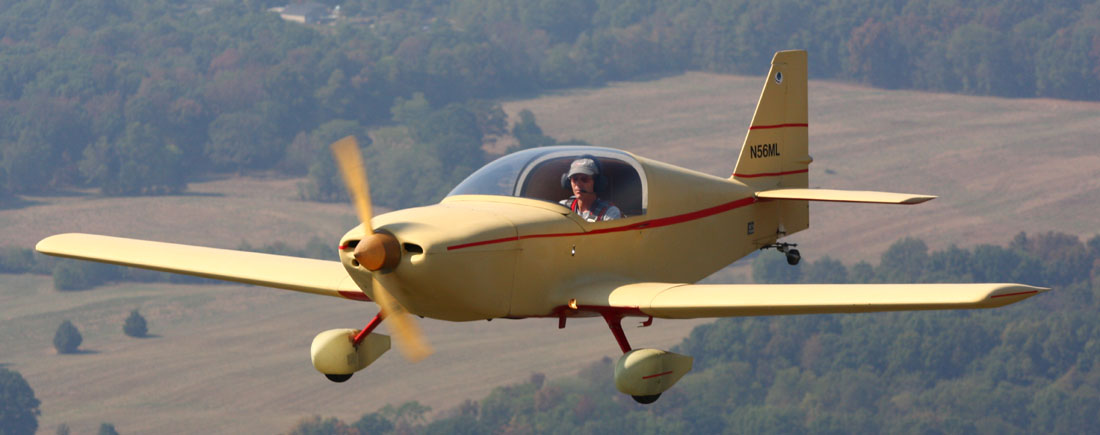
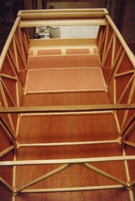
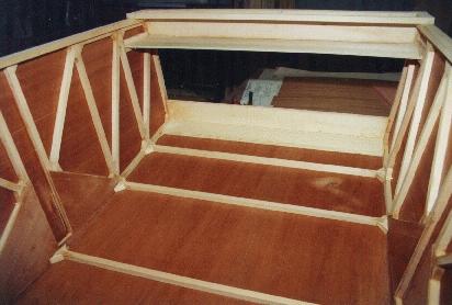
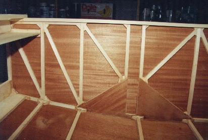
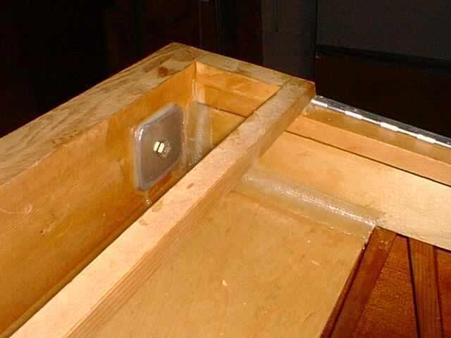
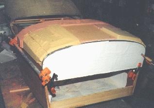
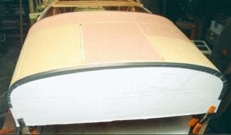
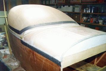
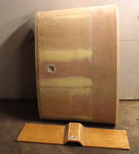
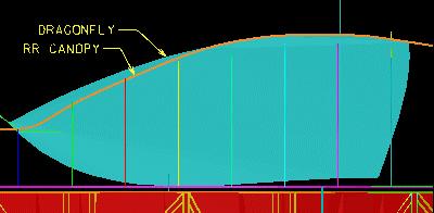
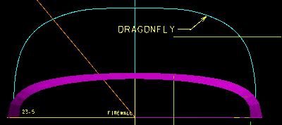
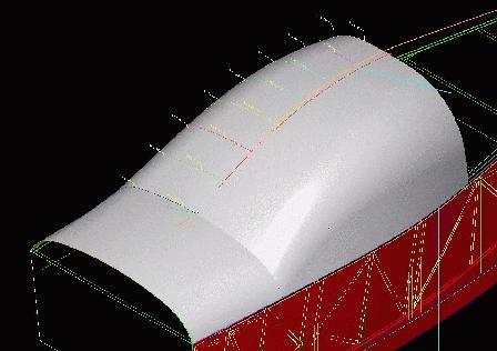
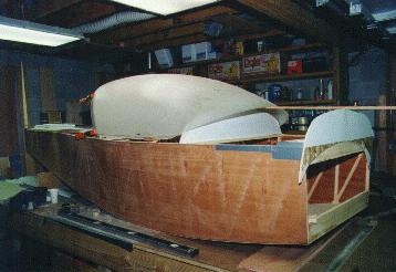
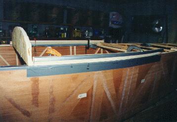
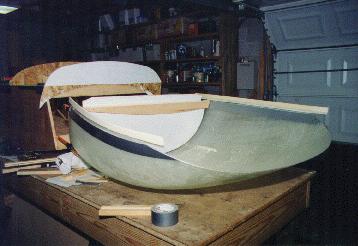
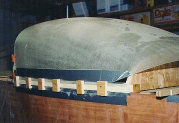
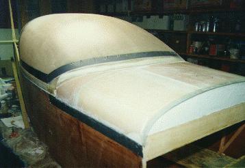
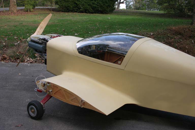
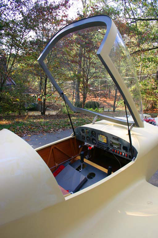
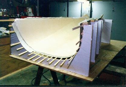
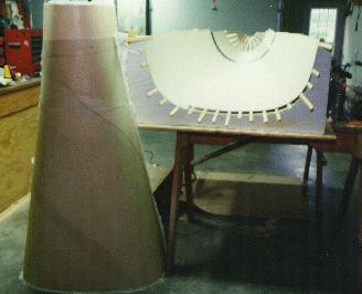
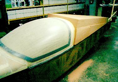
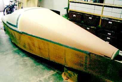
    This is my version of the KR2S. Well, I guess it's not really a KR2S anymore...it has been modified in almost every conceivable way, with only the basic fuselage shape retained. I'm using different airfoils for all flight surfaces, different flap and aileron planforms to increase control effectiveness, redesigned control system, Dragonfly canopy, lots of aerodynamic details for maximum efficiency, and an engine that's almost twice as powerful as the plans call for. It's far from complete, but I've started flying it anyway! This plane will be an experimental test bed for even more improvements to the design, including tufting and wing tip optimization.
    • Empty weight: 760 pounds
    • Gross weight: 1200 pounds
    • Fuel capacity: 16 gallons
    • Top speed: 191 mph TAS (true airspeed) with 3100cc Corvair engine and Sensenich 54x54 prop (turning almost 4000 rpm), 184 mph TAS with Sensenich 54x58 (but turning only 3400 rpm, and burning less fuel).
    • Fuel consumption: I get 42 mpg while flying at 160 mph TAS at 10,000' running "lean of peak", which is how I always fly at altitude.
    • Stall speed: 57 mph with split flaps deployed, 62 mph "clean"
    • Glide ratio: 11.8:1 engine at idle or engine stopped (almost the same number)at about 80 mph, averaged from 10,000' to 2,000'.
    • Propeller: currently a wooden Sensenich 54 x 58. I've tested at least 10 different props, and this one gives me the best speed and economy with a reasonably low engine speed.
    • More Performance data (as testing continues)
    Since I've finished my plane, I've undergone a bit of a transformation from crazy airplane builder to real pilot and aircraft owner. One year I put over 45,000 miles on my airplane (that's twice around the earth), yet my car only saw 6000 miles. I now use the airplane as my personal time machine...turning long, monotonous trips into a pure pleasure, both going and returning. I can fly my plane and get somewhere at least 3.5x faster than driving, and I'm not a time waster when it comes to driving either! My airplane typically gets about 40 miles per gallon at my usual "economy cruise speed" of 160 mph at 9500' or 10,500', far better than my Volkswagen GTI or my wifes's Audi A4. If I'm not in a hurry, I can get 51 mpg if I slow down to 143 mph TAS. I burn 93 octane auto fuel (same as the cars), so clearly flying is cheaper than driving, and I don't have to stop and buy lunch!
    In the last few years I've flown to Wisconsin, central Florida, South Carolina, West Virginia, northern Illinois, northwestern Iowa, and everywhere in between. I'm planning a trip out west to see the desert one of these days. I am so eaten up with flying that I basically don't do anything else...sort of like a meth addict. My basement shop is a mess, I never watch the news anymore, I haven't washed my car in months, and I can't even find time to buy new underwear or socks. But I do manage to keep several 5 gallon cans of 93 octane fuel in the hangar (I wouldn't want to run out), my flight bag in the trunk of the car, and the key to the plane with me at all times, just in case.
    And it's obvious to those who've seen my plane that actually making it look nice (or anything short of embarrassing) is way down on my list of priorities. I'm flying the crap out of this thing, enjoying every nanosecond of it, and I don't see any relief in sight. On a recent afternoon after work I was considering going flying (despite having flown to South Carolina and back the day before) but thought I'd try to hang around and visit with the family a little, when my wife says "why are you not out flying....it's GORGEOUS out there!" This worries me a little, because I don't think life is supposed to be this good. Next time you see me, I'll probably be the guy that can't find the time to shave...
    Fuck you. We're going to Costco.

  • #2
    The build:

    I started on my fuselage in May of 1994, and finished it by the end of the year, taking a total of about 60 hours, according to my building log. The pictures below are a smallish and not the best quality, because they were taken with a film camera and scanned in.
    The fuselage sides are constructed from 5/8" square spruce. In this view, the upper longeron is on top, and the lower longeron is on the bottom. The firewall wall end is on the left. The upper longeron is defined (in the plans) by a straight line, which I ensured by screwing a straight board down to the table as a guide. As you can see in the photo, I used square blocks placed about an eighth inch away from the lower longeron and screwed to the table with one screw (so it's free to rotate). I then used builder's shims to tighten up the joint by lightly tapping the shim between the block and the lower longeron. Not too tight, because you don't want to force all of the glue out of the joint. Although the plans call for using wax paper beneath the joints, I used 4 mil "builder's plastic" instead. Wax paper leaves a wax residue that will impede future epoxy joints' adhesion. Note the pine spacer (which I probably should have wrapped with duct tape as an epoxy release) that maintains the opening that the main spar will eventually go through.
    "Do I have to go to the trouble of making all of those tiny gussets, when it would be much easier to just cut out little plywood gussets and glue them in place?" you ask. You can build your plane however you see fit. But you should be advised that Tony Bengelis (among others) says that plywood gussets are better than none at all, but solid Spruce gussets are the best.
    If "gusseting" is all you're after, plywood may work almost as well as spruce, but one of the major purposes of spruce gusset blocks in the KR fuselage design is to increase the area of the glue joint between end grain members (verticals) and longerons. If you've ever tried to break a joint without the gussets, it's really easy. With spruce gussets you have three times more area to make that connection, subtantially more than a plywood gusset gives you, and now two of the joints are parallel to the grain, a much stronger joint (stronger than the wood itself)than the end grain joint you'd get without the spruce gusset.

    Speaking of gussetts, Dayton, Ohio KR builder Ron Willett shows us one of many gusset clamps that he used to apply light pressure to his gussets during fuselage construction. The plunger is just a nail, and the spring is from the local spring supply house.
    These gussets, and anything else you glue together with T-88, need only light pressure to make a good connection. Too much pressure will squeeze all of the glue out leaving a weaker joint. I always brush epoxy onto both surfaces and let it soak in for 5 minutes or so, then apply a little more and join the two pieces. After a truss (fuselage side) is constructed, and it's time to skin it with plywood, glue the plywood to the side that was facing DOWN. When you miter your verticals and gussets you try your best to make the joints perfect on the side you can see, but what happens to the side facing the table that you can't see? Since you can't see it while you're fitting and gluing, the joints won't be as tight on the down side, so cover THAT side with skin to both strengthen it and hide it. I didn't have the good sense to do this, so the joints that you see inside my boat are the joints on the worst looking side.
    And one more thing...when you epoxy the skin to the fuselage sidewall frame, trace around the frame lightly with a pencil on BOTH sides of the plywood, and then remove the frame and brush a thin layer of epoxy onto both the plywood's inside surface and the mating side of the spruce frame. Mate the frame to the plywood, and put a small (#4) countersunk wood screw through the plywood into the frame at two of the corners to keep them in aligment (this is easy if you hang the corners over the edge and screw up into the frame). If you don't put these screws in there, or find some other way to "pin" the plywood, it will very likely slide out of alignment before the epoxy cures. Then flip the whole works over and staple the plywood skin using your previously outlined pencil marked out side as a guide, with each staple straddling a continous nylon cord or fine wire (safety wire works well) that can be used to pull one leg of the staple out to aid in staple removal later. When all the staples are in, remove those two little screws (if you use T-88, they'd probably be there forever if you let it cure with them in there) and flip the whole thing back over so the plywood skin is on the work bench, spruce on top. This way the excess epoxy will run down onto the inside of the skin, leaving a nice little fillet in the joint between skin and spruce members when it's all cured. This also gives you the opportunity to wipe away any drips or serious excess epoxy. When removing the staples, first pull the wire/string out to liberate one leg of the staple, and then use a wide-nosed pair of pliers as a fulcrum against the plywood to roll the staple out of the wood.

    The "boat" is formed by standing the two sides up and stretching them around blocks screwed to the table. I used a full size plot on the table to make sure the sides were symmetrical, and a plumb bob with the centerline to deal with the top. This was certainly overkill and not required. This is really not rocket science, although I sure tried to make it that way! Others have been constructed using several trapezoidal jig frames which define both top and bottom dimensions. I'm sure that works too, and guarantees a square fuselage (not that it matters much).


    Completed boat with vertical stabilizer spar and firewall supports installed. A wide angle lense and goofy perpective make it appear warped and twisted, but I assure you, this is one symmetrical fuselage.


    View showing urethane foam installed under cockpit floor for noise insulation. Also shown are hardpoints for rudder pedal installation.


    Firewall details.


    Spar gusset details.
    Fuck you. We're going to Costco.

    Comment


    • #3
      Update: December 2000

      Here's what I did to reinforce the connection between the firewall shelf and the fuselage sides. 3 layers of 1" wide 9 ounce fiberglass tape applied over a fillet of flox will do that job in my application. The aluminum backing plates that accept the engine mount bolts are 2" from the longerons, and measure 2"x2"x.188". Since my mount doesn't connect in the middle of the firewall (like the plans call for) I don't need those two 44 ounce aluminum angles fastened to the firewall and shelves. The plans call for these to spread the loads from the center mounted engine mount out to the longerons. My engine mount goes almost right to the longerons, so I'll save that 5.5 pounds, and use the aluminum for something else!
      What would I do differently given the opportunity? I'd probably use all of the 14 feet of longeron material that Wicks Aircraft sent me, by adding 2.75" to each of the seven bays AFT of the aft spars, yielding a plane 19.25" longer. Another option is to add another bay back there, with the same dimensions as the others. Either way would probably be just about right to improve stability using the stock width horizontal stabilizer. The method you choose to do this may require a little thought regarding the length of the plywood that you'll be adding to the sides, since the scarf joints need to occur over a vertical member.
      Fuck you. We're going to Costco.

      Comment


      • #4
        Horizontal Tail Construction
        written May 15, 1996, revised August 2006...ten years later...
        In an effort to tame some of the pitch sensitivity, a made my horizontal stabilizer 6 inches longer on each side, but adjusted the elevator area to remain about the same as the plans call for. Increasing the horizontal stabilizer area was an effort to increase the horizontal tail volume coefficient. The KR has one of the lowest of ALL airplanes, and since my fuselage was already built, making the tail larger was the only way to increase it to a more reasonable number. Were I to have the privilege of starting over, I'd make the fuselage about twelve to sixteen inches longer (by either adding an equal amount to each of the 8 bays behind the aft spar or by simply adding another 14" bay) so the horizontal stabilzer could be left with stock dimensions while obtaining the same result.
        I also added two extra hinges (for a total of five) to effectively cut the hinge loading and wear in half. Having done this, I was later told that the Austrailian feds have been requiring similar modifications for the same reasons. I tried to make rod end bearings work for the application, but never found exactly what I needed. Dr. Dean did exactly that (see his elevator hinges) and that's how I'd do it if I were starting over.
        For drag reduction purposes, I chose a NACA 63009 symmetrical airfoil for the root and the tip. That 5/8" square tip called out in the plans is certainly quick to build, but probably isn't the hot setup for aerodynamics. Of course we're only talking about a small percentage of total drag incurred, but it all adds up... I also think the higher lift coefficient of this 9 percent airfoil should also offer more control during a stall than the shape that it replaces, and it's a REAL airfoil, all the way to the tip. Not that there's anything wrong with the way a KR2 stalls, of course.
        My first horizontal stabilizer was built the recommended way, using the long 3/16" rod to align the hinges, which were then marked, drilled, and installed. Unfortunately, once the rod is removed, the elevator removed, and you are able to get to the hinges to drill the spars for the AN-3 bolts, things move around sufficiently that your alignment evaporates. I supposed that the trick would be to lightly glue the hinges in place (just in case you have to replace them some day) while the rod is holding alignment, and later drill the holes using the hinge halves as your jig.
        My second horizontal stabilizer was considerably nicer, but took about 60 hours to build. Yes, it will be a while before this bird flies at this rate. The new airfoils were plotted out full size with the spars (same 7" spacing as the plans) located on the plots. Then these plots were glued to 3/32" plywood which were cut out on the bandsaw.
        [img]http://www.n56ml.com/kmlht1.jpg[/ing]
        The "humps" around each spar were provided to allow the spar area to be cut away, so that the rib could also double as an alignment fixture during construction. Also, notice that the elevator and horizontal stabilizer are constructed simultaneously as one continuous piece, maintaining perfect alignment with each other.


        The tapered spars were created on the tablesaw with the same tapering fixture that the newletter printed a few years back. Simply put, it's a straight piece of 1x6 to which the spar is clamped using wooden clamps, at the desired angle. The angle on the blade was also gradually altered during tapering, so that the spars required no sanding to match the airfoil profile. This took an awful lot of thinking (mostly in mirror-mode) and ate up a lot of time, but was worth it in the long run.


        Once the spars were complete, the spar cutout locations in the rib/jigs were removed with a jigsaw. The spars were inserted into the ribs and properly located: the roots at 6" from the centerline, and the tips at the ends. With all the spars aligned and leveled (using a level, a waterlevel, and a straightedge) the hinges were again aligned using the rod and were clamped and epoxied in place between the two spars. All other joints between ribs and spars were also epoxied in place, and gussets added.


        After curing, the humps were sanded off down to the airfoil outlines plotted on the ribs. 3" urethane foam (necessitated by my 9% airfoil) was then epoxied between the spars, and shaped by block-sanding between the ribs with an aluminum channel with 50 grit sandpaper glued to it. The large self adhesive sheets sold at Home Depot type stores for floor sanders works great for this job. The glass was applied per the plans, and the reulting surfaces are impressive. Elevator gap seals were created by sanding the urethane foam with PVC pipe covered with sand paper.


        Most modifications have their compromises, and mine were no exception. Because my tips are airfoils rather than a piece of 5/8" square spruce, they are much thicker, and require deeper spars. That means they are heavier, but also stronger. But as we all know, the design doen't need to be "beefed up" anyway. The extra depth also required 3" thick foam between the ribs, but I simply glued some 1" to some 2" to make it, and ensured that the glue joint would not require sanding.
        Not only am I using a different airfoil for my tail, but for my wings as well. And my wing incidence is set at 1 degree, with 2.25 degrees of washout. Obviously, the horizontal stabilizer incidence will also need to change.

        Since I'm using a main wing airfoil that hadn't been tested with this airplane [at the time I was building], I have made my horizontal stabilizer ground adjustable by adding a 2" x .75" .125" thick aluminum angle on each face of both horizontal spars connecting them to the longerons. This way I can fly the plane at cruise speed, trim it to fly level with no stick input, and land without changing the trim. Then, on the ground, I'll adjust the horizontal stab to reflect what the trim tab is trying to compensate for. By iterating on this procedure, I will eventually arrive at a point where my trim tab will be in line with the rest of the elevator, and my h.s. will be set perfectly for cruise speed with standard pilot and fuel. I will probably epoxy everything in place at that point for safety reasons, assuming no major CG altering modifications are foreseen. Looks good so far. I'll let you know how it works!
        I've had a lot of folks ask me where I found the NACA 63009 and NACA 63005.5 airfoils that I used for horizontal and vertical stabilizers. Well....I cooked them up myself, using a program that Lionheart designer Larry French wrote that uses the NACA equations to create the points. If you'd like a set for your own use, you can download a 1200 dpi pdf file of the templates .
        The file is only 120k, so it can be carried to a print shop and plotted out full size (42" x 15"). This file contains all the templates you'd need for rudder, vertical stabilizer, rudder, horizontal stabilizer, and elevator, plus rounded nose templates for each hinge gap. Note that you'd need taller horizontal stabilzer spars for these to work. This yields a stronger h/s spar.
        Fuck you. We're going to Costco.

        Comment


        • #5
          Jan 2001 - Now that I've had a few years to learn more about things, if I were to build my elevator again, I'd probably use aerodynamic/static balance "horns" that both balance the elevator, and improve the airplane's overall stability. Dr. Richard Mole has designed just such a tail for the KR2S, which can be seen on Dana Overall's KR2S tail . Exact numbers have yet to be released for public consumption, but you get the idea. Just add some balance tabs. This sounds counterintuitive, but Richard Mole is an aerodymacist, and I'm at least willing to give it a try. I can always just cut them off and see what the difference is.
          August 2006 - Several folks are now flying with these tail airfoils (including me), and by all accounts they work just fine. In fact, I have 300 hours on my plane, and because I have yet to add wheel pants or "finalize" the aerodynamics, I still haven't epoxied the horizontal stabilizer in place permanently. I guess that means it works. I'm still flying with the same -.75 degree horizontal stab incidence, and that's perfect with a passenger. With just me and full fuel, I need a little up trim dialed in, so I may try -1 degree of incidence, but I want to wait until all other factors are considered (such as wheel pants) before I do that.
          Fuck you. We're going to Costco.

          Comment


          • #6
            KR2S Forward Deck Construction
            revised March 12, 1997

            I've finally settled on what I think is the best way to make an accurate composite surface. This only works on projected surfaces, those that can be created by putting a template on each end of a piece of foam and sanding to contour. This constitutes the majority of surfaces on the KR2S.
            Having already built a forward deck/fuel tank, I was a little reluctant to start over and do it again. But the thought of 17 gallons of fuel in my lap (along with a battery and several hundred feet of wire!) just didn't sit well with me. Wing tanks began to look better as time went on. Because I already plan to use fuel injection, a fuel pump is required. And because I'm seriously thinking about not using a mag, a backup battery will be required anyway. So I already have the backup electrical system in mind. And since the cg of fuel in the wing tanks is almost centered on the CG of the airplane, shifts in CG due to fuel burn will be imperceptible. The normal forward fuselage mounted header tank, on the other hand, creates dangerously large CG shifts as fuel burns off.
            Which leads to the empty forward deck, or baggage compartment if you so desire. About a year ago, I tried to create this same surface (for what was to become the now defunct header fuel tank) in reverse. I sanded the foam to contour and glassed the outside, hoping that I could remove it, hollow out the inside, and glass it. Wrong. It just curled up into contorted mess. That led to a more carefully thought out method that is, admittedly, more labor intensive, but created excellent surfaces with very little finishing required.

            The first step was to determine the shapes of each end of the deck. This was easy for me, as I still had the templates left over from the fuel tank episode (shown above). These templates are merely the shapes of the firewall on the forward end and the instument panel on the aft end. I then made another set of particle board templates identical to these, except with a 3/8" offset, the desired thickness of my final product.


            These two templates were then fastened together to create a jig into which three pieces of 2" thick urethane foam were placed. This was a friction fit (with the foam resting on 2x2 support blocks) to avoid having foam chunks broken out by glue removal.


            A 4" PVC pipe with 20 grit self adhesive sand paper (made for floor sanders) was used to shape the foam down to what would become the inside of the deck. This takes about 20 minutes.


            I then used the plastic sheet layup method to apply a layer of 5.85 oz fiberglass to the inside surface. This little known method is accomplished by first laying a sheet of 4 mil plastic (builder's plastic from Home Depot) over the object to be glassed, and outlining the shape with a Sharpie marker. The plastic is then laid out on the layup table and glass is rolled out on top of it. The glass is laid out with about two inches of excess border extending past the border defined by the plastic. You now know for a fact that the glass you are wetting out will cover the area intended. Straighten the lines of the BID weave and cut, ensuring that you have a piece bigger than the plastic. Mix up some epoxy and pour over the glass in over a large area using a zig-zag pattern to "stake" the glass to the plastic, squeeging away the excess, but making sure that there are no light areas which indicate insufficient wetting.
            When all is wet, mix in micro with the rest of the epoxy and work it into the foam contour with the squeegee. When all foam has been covered, lay your plastic/fiberglass sandwich on the foam with the glass side down. The plastic makes this step simple, and holds the weave perfectly straight and perpendicular. It's also easier to manuever the glass into position if you don't get it where you wanted it to start with. Once it's where you want it, start forcing the glass into contact with the squeegee, applied to the plastic, kind of like applying a decal.
            Cut the plastic/glass sandwich around the borders of the part, leaving no more than a quarter inch hanging over. Any more and a void will result at the edges because the weight of the excess will separate the glass from the foam adjacent to the edge. Peel the plastic away, and you're almost done. Squeegee the whole surface to bring the glass into intimate contact with the foam and micro. Come back in about four hours and cut the glass to conform to the edges within an eighth inch or so with a razor knife. You can do this later, but it's a lot easier to cut now that later. Let it cure overnight.
            Fuck you. We're going to Costco.

            Comment


            • #7

              This is what you'll have.


              Now you need to prepare the longerons for the hinge mounting system. Piano hinge mounts will allow the deck to be easily removeable by merely pulling the hinge pins. First, screw the hinges down the longerons with number 4 wood screws, spaced every few inches. If you plan to hinge the deck open with the hinges, you'll want to turn one of them opposite to the way I did mine, with the hinge pin outside. I decided that if I were to make mine a baggage compartment, I'd just cut a whole new door into the deck. But at the moment, I don't plan to put anything up there but my battery.


              Now cover the longeron and the hinge that's attached to it with duct tape, so that micro won't stick to them. Attach the other hinge half with the hinge pin (with holes already drilled for the plywood sill), and cover the top side with duct tape, sticky side down. Stick the tape only to the upper hinge half at this point, because you still need to screw the plywood sill to the hinge (see above picture, which is actually on the AFT deck), and don't stick it the part of the hinge that mates to the lower half, since this would prevent rotation.


              Cut a strip of 3/32 plywood that will fit the hinge and the thickness of the deck. Mine was about 5/8" wide and fit nicely between the outer and inner skins of the deck. Flip the hinge half over and screw the plywood to the hinge from the bottom. Fold the hinge down flat and seal the tape down against the longeron, and over the area of the hinge where the pin connects the two hinge halves. You have now completely protected the hinge from being permanently epoxied to itself with micro, so you can work on the connection between the top hinge half and the deck itself.


              You should have something that looks like the picture above, with screws protruding to help hold it all together.


              Prepare the deck by removing foam from the edges of the glass to a depth of 3/8" or so. I used a tiny wire wheel on a Dremel tool. This is the perfect tool for this job, and leaves a nice radius inside. The pockets are for extra micro where each screw is located, for higher strength. After "priming" mating surfaces of glass and foam with straight epoxy, mix up some fairly dry micro/epoxy (just enough so it doesn't run out and make a mess) and fill this channel with it. Leave a little mound that will squish out when pushed down over the foam sill.
              Prime the plywood sills with epoxy and set the deck on top, ensuring that the sills get up between the inner and outer walls of the deck. Push the deck down lightly to fill all of the voids with micro and let the whole thing cure.

              Install your particle board firewall and instrument panel templates at each end of the deck and clamp the foam between them with a straight edge that has sand paper glued to it.


              I used an aluminum channel with a piece of self-adhesive 20 grit floor sander material stuck to it. Sand for about twenty minutes and you'll have the outer shape of the deck finished. Make sure that this foam surface is a perfectly smooth as you can get it. It's a whole lot easier to make this shape perfect now, than it it to try to shape and sand it when it's covered with micro. The last few minutes should be spent sanding side to side, parallel to the templates, to remove any sanding marks. Remove the templates and apply duct tape to the edges, and reposition again. If you want a joggle, for example for the cowling edge to cover on the front of your deck, drop the template a little and sand the left and right edges of your template slightly.


              Now it's time to fiberglass your creation. Again, cut a piece of 4 mil polyethylene a few inches larger than your fiberglass needs to be. Lay it over the deck and mark the edges of your deck on the plastic. You should have a border a few inches larger than your deck all around the guidelines. Cut a piece of fiberglass about the same size as your plastic and lay it out on the plastic, ensuring that the strands of glass are all straight and perpendicular. Pour epoxy on the glass on the plastic and smooth around, being careful not to disturb the orientation of the fabric. Use just enough epoxy to wet out the glass. Squeegee away the excess. You now have a piece of fiberglass with proper weave orientation, complete with outlines and a backing sheet to cut along so that it will be a perfect fit on your deck.


              Prime the foam with runny micro and squeegee away the excess. Lay on the fiberglass and polyethylene sandwich, plastic side up and squeegee thru the plastic to bring the glass into intimate contact with the foam/micro. Once positioned, cut around the edges to within a quarter inch of finished dimensions to reduce overhang.
              Fuck you. We're going to Costco.

              Comment


              • #8

                Slowly peel away the plastic back onto itself (180 degree angle disturbs the glass the least), leaving the glass in place, with weave still oriented perfectly. Squeegee again just to make sure that all air bubbles are gone. Cover this layer of fiberglass with a layer of fine "satin weave" 1.9 oz glass and you'll have no pinholes to fill later. This step is a real time saver, and helps make the surface a little stronger too. OR, you could then apply a layer of peelply to the whole thing, and squeegee it into close contact. Allow to cure completely and remove the peelply if you used it.
                Peelply gives you a surface that's prepared for more overlapping layups later on, but if you need two or three layers of glass on a part, do them all at once. The peelply is used only to either leave a pinhole-free surface (if you're not using the satin cloth), or if you plan to layup something else on part of your layup later.
                Now that your deck is super strong, pull the hinge pins out and pry up between the hinges to pop the deck loose from the longerons. Remove the upper hinge pin from the duct tape which covers the plywood sill, and remove the duct tape. Sand a slight radius on the edge of the sill and apply a layer of fiberglass tape to reinforce the connection between the inside deck skin and the sill. Install the hinge half again, covered with duct tape to hold the tape in place while curing, and reinstall the deck on the plane to cure. After cure, remove the hinge and the tape, and epoxy the hinge half to the skin permanently.

                The final result is a forward deck skin 3/8" thick and very strong. You may then build a fuel tank or a baggage compartment under it.
                Fuck you. We're going to Costco.

                Comment


                • #9
                  That's pretty cool.
                  "It's another burrito, it's a cold Lone Star in my hand!"

                  Comment


                  • #10
                    KR2S Fuel Tank Construction
                    created April 12, 1996...updated August 2006

                    Fuel tank/forward deck. My tank was scratch built using 1/4" thick 4 pound density Clark foam with two layers of 5.85 oz glass cloth wetted with Safety Poxy II sandwiched on each side. One 5 quart epoxy kit is all that is needed for layups and assembly. This was before I learned about vinylester, which is universally agreed as the one fuel proof resin that's best for fuel tanks.
                    I modeled my tank in 3D on a CAD system in order to maximize fuel capacity, while providing ample room for instruments, avionics, and legs. I put my avionics cutout on the left side, because with a center stick, my left hand will be free to operate GPS and radios. Given my experience with the pitch sensitivity of the KR2, I don't think it's wise to try to fly one hands off. Originally, the fuel capacity of my design was 21.5 gallons, but after reflecting on the consequences of having that much "volatility" in my CG range, I decided to reduce it to 17.5 gallons. I may add a 6 gallon wing tank to the passenger side wing.
                    The first step to constructing the tank is to make a sheet of fuelproof "plyfoam" to make the tank from. Spray or brush a layer of PVA (poly vinyl alcohol, available from Alexander Aeroplane, Wicks, and others) release agent onto a quarter inch piece of glass that's already been waxed with mold release wax (like Partall). I picked up a 3' x 3' piece of salvaged glass for $15. Then lay up two layers of 5.85 oz fiberglass on top of the PVA, NOT being careful to keep the resin to a minimum. This is one place where excess resin is a good thing. Immediately micro one side of a large pice of Clark foam and stick it to the fiberglass. Squeegee the clean side of the foam to ensure direct contact between the micro'd side and the uncured resin/fiberglass. Then apply micro to the top of the panel and lay up two more layers of fiberglass, and squeegee again. The end result is a "plyfoam sandwich", with two layers of fiberglass on each side of the 1/4" foam.
                    Fuck you. We're going to Costco.

                    Comment


                    • #11
                      Construction Templates
                      Decide on the shape of your instrument panel and draw a template for it. This is basically a mock instrument panel, and will extend to the outside of the two longerons, and will represent the outer shape of your forward deck. I made mine 7.5 inches taller than the longerons, with a nice elliptical shape, and it extends about 2" below the top of the longerons. Use the firewall template from the plans (or design your own more pleasing shape, like I did) as the front template for the tank. Once your templates are drawn up, cut out a firewall and instrument panel contour out of 3/4 inch particle board to be used as sanding guides, and clamp them in place. The aft end of the tank will be something that looks like a cross between the firewall and the instrument panel. If you make it a little large, it will simply be sanded to contour with the rest of the top of the tank.. The aft end of my tank is 17" from the rear of the firewall, which yields around 17 gallons of fuel, 7" of space for instruments, and 14" of space for radios

                      You also need two baffles for the interior. I made the bottom of my tank slope down as it goes aft, so that in a level or nose-up attitude, the fuel pickup will always be covered with fuel. There is also a sump in the center. This ensures that in straight and level flight, only about two ounces of fuel is unusable.
                      Position the foward end of the tank against the firewall, and the aft edge about 7" forward of the instrument panel. Cut out the two pieces which will sit on the two plywood firewall shelves and one which connects the two pieces together. Edge glue them together (with the smooth glass-like surface facing the inside of the tank) using flox and resin, and layup two layers of glass tape at each seam, overlapping in the corners. I used one strip of 1" tape, and one layer of 2" tape on top of that. The end result will be four layers of glass in each corner, with losts of resin to ensure against pinholes.

                      Install the two tank sides and the two baffles along with the aft end of the tank, edge glueing all joints with flox and resin and clamp lightly together.

                      Here, the bottom is being temporarily installed while two more layers of glass tapes are used to create flanges between the side walls and the bottom. Peelply is used to prevent the bottom from sticking to the flanges. After curing, the bottom is removed so that the top can be constructed and sealed from the inside. Later, lots of resin is spread on the flanges, and the bottom is reinstalled permanently.

                      A view showing the bottom of the tank temporarily installed during flange creation. Duct tape was used during the process to hold the bottom tightly against the sides of the tank. No tapes are installed on the outside of the tank yet, but there's no reason why they can't be.

                      The top of the tank is constructed from two inch urethane foam, with the bottom side laid up with two layers of fiberglass on glass again, as before. It is then trimmed to fit into the top of the tank in three or four pieces. The fiberglass layer on the bottom of the foam should be a nice tight fit inside the top of the tank.

                      Flox them in place with a generous fillet in all corners. Then, working inside the tank from the bottom, immediately install the two fiberglass tapes around all joints again.. For mounting, I installed piano hinges between the longerons and the tank sides, where the two meet. The fuel tank is now removable by simply pulling the pins. Until these hinges are installed, the tank is actually resting on the ears of the front and rear tank walls.
                      Sand the top of the tank to contour using a sanding block long enough to span both instrument panel and firewall plywood templates. Cover the longerons with duct tape to prevent damage to them.

                      The resulting top surface is now ready to be 'glassed.

                      Lay up the top of the tank with one layer of 5.85 oz fiberglass cloth and one layer of fine weave 1.5 oz cloth on the outside. Squeegee on peelply over the tank top to absorb excess resin. After curing, use micro to blend the edges of the tank to the fuselage sides.

                      Install the fuel cap either forward or aft, depending on whether your gear is conventional or tricycle, and flox into place, reinforcing from the inside with fiberglass tape.

                      Install fuel sending unit. I used a universal VDO adjustable sending unit, part number 226-001, available for about $30.00. Don't forget to connect a ground to it. Ensure that there are passages at the top of the baffles on each end for air to pass through, and apply epoxy to any exposed foam. After installing the finger strainer in the tank bottom, epoxy the bottom on, and reinforce with the now familiar two layers of 'glass tapes.
                      You should now pressure test your tank with about 1 psi of pressure. Too much and it'll blow! You can use oxygen from your oxy/acetylene welder tank, because it has a very accurate pressure regulator. Yes, the area must be well ventilated.
                      Revision, later: Vinylester is the resin of choice for fuel tanks. It is almost completely impervious to most chemicals, including aviation and auto fuel. This is what I used to build my wing tanks with. It stinks, it's hard to work with, and I hate it with a passion, but it's the ticket for fuel tanks! One more thing I've learned is to make the tank panels out of 3 layers of thoroughly wetted-out glass. Or better yet, consider aluminum, which can be tested and then merely bolted in place!
                      Fuck you. We're going to Costco.

                      Comment


                      • #12
                        Canopy Frame Construction Page
                        created August 1996, updated Oct 20, 2004

                        OK. Here's a Dragonfly canopy which needs to be mounted to a KR2S fuselage. How you gonna do it?
                        I first placed the canopy on the fuselage. trying to locate it where I thought I'd have enough headroom, and so that its forward edge would not be over the fuel tank. That turned out to be at a location about 17.5 inches from the front edge of the fuselage.

                        I took two pictures of the Dragonfly canopy, one from the side and one from the rear. The curves were then scaled and normalized to proper dimensions and placed on my 3D KR2S model. curve.

                        These photos were then digitized into bspline curves in a CAD program. I used a Dragonfly canopy (the source is listed at the bottom of this page). I chose it because it is designed for a plane that is roughly 8 inches wider than the KR2S, And because it is thinner and more flexible, would be easier to deform to fit my 3" wider fuselage. This canopy can easily be used on stock width KRs, as well as those stretched 8" or so. The R/R KR2S canopy is 3/16" thick, and may be quieter than my 1/8" thick Dragonfly canopy, but I can think of many other noise sources which would factor into that equation. The Dragonfly was also about two hundred dollars cheaper, and shipping was $70 rather than $160, but that's a geographical consideration.

                        Front view.

                        The two 2D curves were then turned into a 3D surface using the side view curve, the upper longerons, and the front view

                        With the 3D model built, I was able to design a nice looking firewall and instrument panel which would blend with the canopy.
                        Once these were designed, I plotted out full size templates for the firewall and panel. These were used to build the fuel tank and forward deck. It's easier to build a canopy frame if the forward deck is already in place. But you need a canopy in place to ensure that it fits forward deck that you're building...

                        The canopy frame rails which sit on the longerons were made from 1/4" Clark foam which had been covered with 2 BID of 5.85 oz glass on each side (a foam sandwich). I made a 2' x 4' sheet of it, and hot glued it lightly across the longerons. A router with a laminate trimming bit was then used to cut the frame sides to a perfect match with the upper longerons. I actually used three layers of the sandwich on my frame, but only because all I had was 1/4" foam. One layer of 3/4" foam would work almost as well, depending on what kind of canopy latching system you plan to use.

                        I then stripped off a 1.5" strip of fiberglass from a piece of sandwich and epoxied it to the edges of the canopy to provide a connection between the outside of the canopy and the frame rails The frame rails which had been built in place using the router were then offset toward the center of the fuselage just enough to allow for the thickness of the fiberglass which was added earlier.

                        The canopy was then placed on the frame side rails, and epoxied and microed into place, using wooden blocks strategically located to force the canopy (it's a Dragonfly, and therefore, a few inches wider than my fuselage) to conform to the fuselage and frame rails. After curing, three layers of 9 oz fiberglass tape was added to each side of the canopy where it meets the frame.
                        After the front deck was built, I covered it with duct tape and glass the forward edge of the canopy to the top of the deck. A reinforcement consisting of foam and glass was then added to the inside of the canopy to stiffen it up.

                        Here's the final product, almost. Next is to do something about the front edge, where it meets the fwd deck. I blended it into the deck, and then cut the canopy away, leaving a lip for the canopy to fit up against on the forward end. This provides a good wind and rain seal, and is a perfect fit from deck to canopy, since the canopy frame was made using the deck as a mold.
                        Fuck you. We're going to Costco.

                        Comment


                        • #13

                          The hinges are geometrically similar to VW Beetle hinges, but are made from 1/4" 7075-T6 aluminum for maximum stiffness. The brackets were plotted out from a CAD file file, and glued to the aluminum to ensure accuracy. Here's a full size pdf version .

                          The two attach brackets were made from 1/16" aluminum, but I should've made them thicker. These attach to the canopy sill with flox, screws, and carbon fiber reinforcement.

                          These reinforcements are bolted to the hinges (which are fastened to the bracket, which are fastened to the hinge bulkhead) with #6 screws and nuts.

                          Here the brackets are shown with a bunch of holes drilled in them, so that the flox and penetrate the hinge and connect to the carbon fiber overlayment.

                          Duct tape is placed under them so flox will stick only to the canopy bottom, and not to the forward deck.

                          The hinge assembly before mounting to the brackets.

                          The hinge attach bracket is visible under the forward deck. Here the forward deck is being floxed to accept the panel mounting nutplates.

                          The back side of the panel, ready to be squished into the flox in the aft edge of the forward deck. Canopy hinges

                          A view of my canopy hinges mounted to their bulkhead under the front deck.

                          This is my final canopy/front deck interface. The hinge is a 1/4" 7075-T6 piece for maximum stiffness.
                          Fuck you. We're going to Costco.

                          Comment


                          • #14
                            Front view. Although I used duct tape around the Spray Lat coating, I quickly learned that duct tape and masking tape are NOT the thing to use. They both leave a nasty residue that can etch the acrylic and ruin the canopy. Electrical tape is the way to go....it's easy to put down in whatever shape you want, and if it leaves any kind of residue, WD-40 wipes it right off. Make sure you cover the Spray Lat near the edges with three or four strips of electrical tape (wide, not deep) so that no paint or primer will come in contact with the Spray Lat. When it came time to peel the Spray Lat away, I learned the hard way that primers adversely affect the coating, making it very difficult to remove.

                            Canopy and instrument panel installed. Panel is covered with a CAD plot of what my instrument panel will look like.

                            Canopy struts have been installed. They're each rated at 20 pounds of force when extended, and have internal valving to slow extension considerably. I got them from Magnus Mobility Systems in Orange, CA at (714) 771-2630. Part number is 752940. They are 585mm long extended, with a 250mm stroke (the best ratio I could find). They are made by Stabilus, and have the familiar trade name of Lift-o-mat (TM). You'll also need four ball studs (#102431). I figured for such nice struts, I was going to pay dearly, but they were only $17 each. That sure beats the $5 each that I paid for some from the junkyard, which turned out to exert 60 lbs of force each! They would have catapulted my 18 pound canopy half way to town.

                            I tried to think of a better way to fasten this mount to the longerons, but bolts won in the end. 20 lbs is a lot of force, so they really needed to be mounted on top. And this location gives the highest opening of the canopy. I reinforced the longeron with plywood on the bottom.

                            The ball studs that mount to the canopy were screwed into 4130 inserts that I threaded prior to floxing into the canopy frame. I really worried about the strength of my frame, but I haven't even gotten around to floxing these in yet, and they're plenty strong. The one place that really needs to be strong on a canopy using this setup is where the hinges attach at the front. Lots of carbon fiber would be a good idea.

                            The canopy opens almost 70 degrees, leaving plenty of room to get in or out. I've been told that these should be mounted with the cylinders up, and rods down, so don't mount them as I show here! Otherwise the seals can go bad in about 6 months, but I haven't seen any evidence that this is a problem (after 5 years).
                            Before I put these struts in, I was concerned that this system would be flimsy. It's actually pretty strong, but you can't treat is like you would the hatch on your car. The one place that really needs to be strong on a canopy using this setup is where the hinges attach at the front lip of the frame. Lots of carbon fiber would be a good idea. Although I think mine will work just fine, I'd probably use a method similar to what the Bam-Bi uses (see John Martindale's canopy), which is an easier, stronger, and more stable means of attaching the canopy to the airplane. Or maybe even the nylon roller method (detailed in Bengelis' book) that was used on the Perry Area 51 plane . There are more pictures of this plane on my 1997 KR Gathering page.
                            Update, as of October 2004

                            One thing I learned today was that the latex coating on the inside and outside of the canopy ages with time. After a few years, it gets sort of brittle. Even after 8 years, mine still peeled off, except in the areas where the latex has been "compromised" with primer and paint, especially Smooth Prime. Wherever Smooth Prime had come into contact with it (which was all the way around the edges), the Spray Lat had become very brittle, and practically fused itself to the plexiglas. I spent several hours trying to peel it off with my fingernails, old credit cards, spatulas, etc, but the final solution was to soak the junction with WD-40 and let it soak a few minutes, and then I could peel away another quarter inch or so. This works best when you start at the top and peel until you get to the the primer, and then fill the horizontal junction crack with WD-40 (see photo above). Once I figured out the process, it only took about an hour to finish a chore which I had been convinced was going to take me a couple of days!

                            Here's the final result. Not too bad looking, eh?
                            Fuck you. We're going to Costco.

                            Comment


                            • #15

                              Here's the problem. What to do with that gap between the canopy frame and the tail? Saran wrap?
                              FIRST ATTEMPT:

                              My first move was to create a CAD solid model (using MicroStation) of the shape of my aft deck. A roll bar was constructed and temporarily hot glued to the rear of the canopy frame. The above photo is of my first attempt at female mold construction. The inverted templates were used to define a shape to which formica was attached

                              PVA mold release was sprayed onto the formica form and allowed to dry. It was then waxed and buffed. One layer of 5.85 oz BID fiberglass cloth was then laid up on the form. Immediately afterward, 1/4" 4 lb density Last-o-foam was microed on one side and placed in contact with the fiberglass skin, and sandbagged. Here is where the problem lies. You really need to pull a vacuum on this whole affair to ensure that no air pockets or voids exist between the foam and the skin.

                              After curing, I removed the sandbags and microed the foam again, and applied another layer of 5.85 oz BID glass. This thing was very stiff, and took proabably 50 lbs of force to deflect 1/2 inch between the two legs of the "U" shape that it has become. And it only weighed 8 pounds (maybe high, but call it a roll bar!) But because of the air pockets (I had two 6 inch square voids near the smallest radius part towards the tail), I trashed it. Besides, it changed shape ever so slightly because of differences between my female mold contour and the shape canopy frame / roll bar's rear surface. And it simply has to have a perfect fit there. So the preceding was how NOT to make an aft deck. I had about 40 hours in it, but at least I could use the mold as a tool to build it the right way, so all was not lost. I decided that just MAYBE, the KR manual detailed the easiest, most accurate way to do this, although it sure doesn't look like it at first glance. Which leads us to....
                              SECOND ATTEMPT:


                              I cut three pieces of 6" urethane foam into pizza like slices that would define my aft deck. The thinner stuff detailed in the manual would be fine, but I only had 6" lying around the house, and it's less likely to deform while sanding. Two 6 foot piano hinges were fastened to the top longeron, to provide a means for making the rear deck removable by simply pulling the hinge pins. After covering the critical hinge joint with duct tape, I microed the foam blocks to the hinges.

                              I installed an elliptical template at about the horizontal spar location to use as my contour template, and sanded the foam down to contour between the template and the rear of the canopy frame. I used one of my main spar caps with 20 grit self adhesive sand paper stuck to one face, which is just about the perfect length for this job. It took about an hour and a half to completely sand the outer contour. If I had it to do differently, I'd make the deck before even thinking about mounting the horizontal stablilizer. I had the two plywood bulkheads mounted already, and was constantly bumping them with the spar cap. Not good. Don't let it happen to you.

                              The roll bar was sanded to outer contour along with the rest of the aft deck. About .06" of foam was then removed between the two vertical edges of the roll bar so that 5 layers of 2" 9 oz. fiberglass tape could be floxed and glassed into place between them to complete the roll bar. Two layers of 9 oz BID fiberglass about 8 inches wide, which extended from the canopy (duct tape) across the canopy frame and roll bar, and onto the aft deck. This would help retain the canopy to the frame, and strengthened the roll bar to aft deck connection. Next, the whole deck was laid up with a layer of 5.85 oz cloth, immediately followed by a layer of 1.95 oz "silk weave" fiberglass. This fine layer of glass doesn't require much epoxy (in fact, it soaks up some of the excess from the first layer) and provides a very smooth surface which requires very little filler for pinholes. And as a bonus, the skin is now just a little more resistant to penetration.

                              After curing, the canopy was cut apart from the aft deck with a razor knife and removed. The hinge pins which now secure the aft deck were pulled and the deck was removed.

                              The deck was then hot glued to the female mold that I had made earlier, so that as material is sanded away from the inside, the outer shape is still retained.

                              It took about two hours to sand away the inside contours of the aft deck, mostly using the same tool I used for the outside contour, and a new tool made from an 8 ft length of 4" PVC pipe covered with 36 grit self adhesive sand paper. The foam was sanded down to 1/4 thick at the rear, to about 2" thick at the top front edge, where the integral roll bar attaches. That's a lot of foam to be carrying around, but it makes the deck a sort of continuous roll bar in the area that matters most.
                              Fuck you. We're going to Costco.

                              Comment

                              Working...
                              X